Designing power protection components – UPSs, emergency lighting inverters, generators and IPSs – into a healthcare electrical distribution system can be challenging. The evolving risk and resilience needs of each department must be balanced against budgetary restraints, while also complying with all relevant legislation.
In this article, Alex Emms, Operations Director at KOHLER Uninterruptible Power, examines the issues and offers some practical ideas for design solutions.
Healthcare estates, from GPs’ surgeries to large acute hospitals, require power infrastructures that can be complex and challenging to set up and maintain. Healthcare involves many specialised functions, with steady growth in both the volume and type of applications needing electrical power. Additionally, such applications, with their healthcare dimension, are typically critical and demand power of good quality and high availability.
Accordingly, it may be tempting to simply design in the highest possible resilience across the entire estate, to avoid the possibly extremely serious consequences to human wellbeing and business continuity of a system crash. However, to do so could well exceed available budgets, while also creating unwelcome complexity. On some sites, there may not even be room to accommodate an excessive amount of protection equipment.
So, a realistic question for healthcare decision-makers could be: ‘How can I find the balance between investment and resilience that’s most appropriate for the criticality of any given application?’ – and they can find answers to this question within the Department of Health’s Health Technical Memorandum 06-01: ‘Electrical Services supply and distribution’ document. The document classifies the levels of risk that loss of electrical system supply can pose to both patients and to business continuity. This provides a background against which an appropriate solution to each application can be designed, where resilience levels are carefully balanced against costs. With this background, the document discusses best practice and gives reference to standards related to the design, installation and maintenance of electrical services.
In this article, we look at the implications of the HTM 06-01 document from a healthcare power protection equipment supplier’s perspective. We start with a brief overview of the diverse application types found across a healthcare estate, and continue by considering how the document assigns patient and business continuity risk classifications for such applications. We then discuss the role of power protection components within such an infrastructure.
Healthcare estate applications
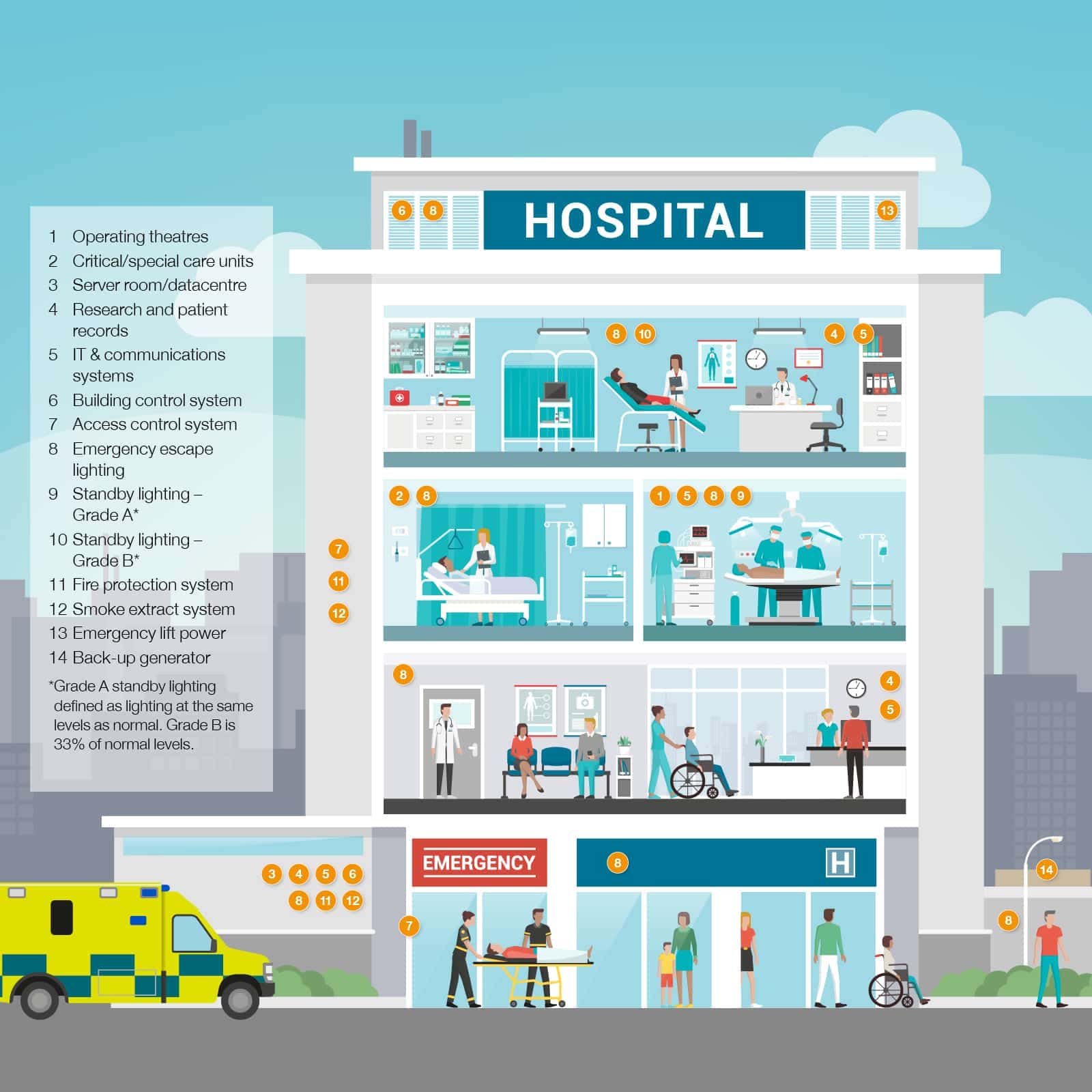
Central to a healthcare environment is equipment directly related to the clinical treatment and safety of patients. This can be found in highly-critical areas such as operating theatre suites, critical care areas, cardiac wards and accident & emergency resuscitation units. There are also less critical locations such as maternity areas, endoscopy rooms, general accident & emergency, and MRI imaging, as well as general patient care and outpatients.
Additionally, the medical IT system provides a monitored, isolated, floating power supply, which will sustain the first single earth fault.
A modern site is also highly dependent on its IT and communications equipment, even though it isn’t directly handling patient treatment. This includes server rooms and data centres, individual PCs, research, and patients’ records.
Finally, there are all the building management and emergency services. These include emergency escape and standby lighting, fire protection and smoke extraction systems, and access control systems.
In practice, there are not always sharp distinctions between patient-critical and business continuity criteria. For example, loss of access to patient records may prevent a doctor from proceeding with a patient’s treatment. And a video link may not be obviously patient-critical – unless a distant specialist is using it to provide remote instruction on an operating procedure, or by students to remotely view an operation.
The continued growth of the IoT and 5G’s upcoming rollout will also create further applications that demand secure power. For example, 5G’s low latency means that performing operations remotely over a communications link becomes possible. Maintaining this link then becomes a patient-critical rather than a business continuity issue.
Classifying the risk from loss of supply
An electrical system failure can occur at any point or at any time in any electrical system, regardless of the design standards employed. The design and installation of electrical systems inherently allows failure (by operation of a protective device) to minimise the risk of danger and/or risk of injury.
The design approach should cater for maintaining an electrical supply within specific time periods for patient and staff safety. These times can be defined as a supply restored within:
- greater than 15 s;
- less than 15 s, but greater than 5 s;
- less than 5 s, but greater than 0.5 s;
- less than 0.5 s;
- no-break
The design process should verify that single points of failure leading to loss of electricity supply are minimised by providing the appropriate level of resilience at the point of use.
HTM 06-01 considers risk of loss of supply in two main elements.
- clinical risk (subdivided into patient and non-patient areas); and
- non-clinical business continuity risks (subdivided into medical services and engineering services)
Small healthcare premises such as GP practices typically fall into lower risk grades, while large, acute healthcare premises and above may well have departments in all grades. The relationship between premises and grades isn’t fixed; instead it depends on individual circumstances and assessments.
HTM 06-01 defines five clinical risk grades (A -E) and four business risk grades (I-lV), although these could be simplified or extended if necessary. Fig. 1 summarises the clinical or patient risk classifications.
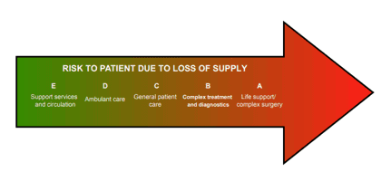
Fig 1: Risk to patient safety due to loss of supply
Risk grade E: typically – support services and circulation: These areas may include circulation spaces, waiting areas, offices and non-patient care areas. Consequently, electrical supply loss does not immediately affect the clinical treatment or safety of patients.
Risk grade D: typically – ambulant care: these areas may include patients in consultation (excluding examination) or general out-patient areas. Supply loss may give rise to disruption, inconvenience and a reduced environmental quality but would not directly compromise clinical treatment and safety. There may be a business continuity risk if these areas are not connected to the secondary power supply (SPS) for failures lasting for several hours.
Risk grade C: typically – general patient care: Medical monitoring or medical test equipment such as electrocardiograms may be connected externally to the patient’s body for a short or intermittent time. Clinical treatment and patient safety will not be immediately compromised by an interruption of electrical power. However, any interruption should be limited to less than 15 s together with other engineering services used in the support of the clinical treatment such as medical gases, hot and cold water, heating, ventilation and air-conditioning (HVAC), and communications.
Risk grade B: typically – complex treatment and diagnostics: these areas may include maternity, endoscopy rooms, accident & emergency general/minors, therapy rooms, ultrasound and other locations. Patients may have medical monitoring or test equipment connected externally to their body for prolonged periods. Any interruption of the electrical supply to medical equipment should be limited to 15 s. Consideration may be given to providing an alternative electrical supply (tertiary power supply such as a UPS) with a no-break or within 0.5 s subject to the range of patient treatment and resilience of equipment used. Other engineering services used in support of clinical treatment should be connected to the SPS within 15 s of any electrical supply interruption.
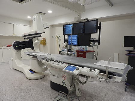
Risk grade A: typically – life support or complex surgery: these areas may include operating theatre suites, critical care areas, catheterising rooms, accident & emergency resuscitation units, MRI and other locations. Where supply disconnection represents a threat to life an alternative source such as a UPS must be available within 0.5 s or as a no-break supply if critical medical electrical (ME) equipment to be used will not continue to function without a reset after a 0.5 s break.
A UPS may be specified just to provide backup for returning an interventional angiographic system’s tilting table to CPR position, allow basic fluoroscopy for catheter removal or allow full system operation. Only a proper clinical assessment can determine the level of power supply needed, balanced against the costs of such systems.
Other engineering services used in support of clinical treatment should be connected to the SPS within 15 s of any interruption of the electrical supply.
Whatever the risk level, the requirements of escape lighting, fire alarm systems or other emergency systems should be provided from a local tertiary power source such as a UPS.
Standby generators may be considered where the loss of electrical supply should be limited to 15 s.
While the above categories classify clinical risks, there are numerous supporting elements and departments essential to continuity of care and business continuity. The impact of failure on these services should be assessed on the same basis as the clinical risk, as summarised in Fig.2.
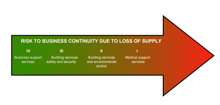
Fig.2: Risk to business continuity due to loss of supply
Risk grade lV: typically – business support services: These include finance, stores, laundries and workshop areas. In general, an electrical supply interruption may not immediately compromise the treatment or welfare of patients. It may be appropriate to provide a UPS to allow certain systems such as computer applications to shut down safely.
Risk grade III: typically – building services life safety and security: The requirements for these facilities are covered by various applicable standards and legislative documents. Typically, battery packs or UPS systems will support such requirements. An electrical supply interruption could compromise patient safety and welfare. An understanding of the need for maintenance and the capacities of any such battery packs employed on these facilities is required.
Risk grade II: typically – building services environmental control: The building services environmental control systems will include HVAC systems, hot water services, energy centres and building energy management systems. In general, an electrical supply interruption would compromise the treatment or welfare of patients. A UPS should be provided to allow certain systems such as computer applications to be shut down safely.
Risk grade I: typically – medical support services: The medical support areas are departments such as sterile services departments, laboratories medical records, and physiotherapy. An interruption of the electrical supply may represent a disruption to patient treatment or welfare. A UPS should be provided to allow certain systems such as computer applications to be shut down safely.
Irrespective of the risk grade, electrical load management systems may prove useful if the supply interruption period extends into hours. Escape lighting requirements should also be provided from a tertiary power source such as a UPS.
Implications of the risk classification systems
Consideration of the above clinical and business risk classification reveals a number of key points. Firstly, HTM 06-01 believes that system resilience, at a fundamental level, starts with having dual power supplies. In the words of the document: “The required system resilience can be achieved in two basic ways: first, by having an alternative power supply and, second, by having alternative distribution cables and/or routes; both may be engaged by automatic changeover with manual bypass.”
However, the document also states that this resilience can be enhanced at the final distribution board with the use of tertiary power supplies such as UPSs, or inverters for emergency lighting. Additionally, the risk classifications note the role of generators in limiting electrical supply interruptions. These are all specialist products that call for significant expertise, both in their selection and in their integration into the healthcare site’s power infrastructure. KOHLER Uninterruptible Power (KUP) is well-placed to help healthcare system designers, installers and users with these issues; they offer a consultative approach based on many years’ experience in supplying all these products, as well as isolated power supplies.
The products themselves have features that allow users to follow HTM 06-01 standards and best practices, while also implementing the document’s classification concepts; designing in components that are cost-effectively matched to requirement, without compromising safety. Below, we give practical descriptions of tertiary (UPS and inverter) and secondary (generator) power products currently available, and show how these can help designers meet healthcare electrical installation requirements.
Modular UPSs and healthcare applications
Early double-conversion UPSs used a transformer-based design, which made them relatively large and heavy. A 100 kW system, for example, would be implemented as a single, floor-standing unit; to build in resilience through redundancy, a second such unit would be needed. This would consume significant extra floorspace and capital cost, while providing unwanted levels of extra capacity. Additionally, as each unit could never be more than 50 percent loaded, electrical efficiency would be low, with high cooling requirements.
The advent of transformerless UPS technology has meant that UPS implementations could become considerably smaller and lighter. Consequently, UPSs can be built as small rack-mounting modules, rather than as a monolithic floor-standing unit. Fig. 3 shows KUP’s KOHLER PW 8000DPA modular UPS system; this can accept up to ten 10 kW or 20 kW modules in one free-standing frame. Additionally, configurations can be changed to substitute internal batteries for power modules. Alternatively, the 19” rack version can fit into existing cabinets while accommodating up to four 10 kW or 20 kW modules. Expansion is easy, as modules can be plugged in – or removed – without even interrupting power to the load. Redundancy is efficient; a 100 kW load for example, could be supported by six 20 kW modules with N+1 redundancy. Utilisation is 83%, compared with 50% for the two 100 kW units that would be needed for a 100 kW monolithic solution with N+1 redundancy.
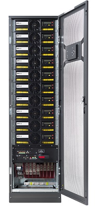
Fig.3: KOHLER Uninterruptible Power’s KOHLER PW 8000DPA modular UPS
Some healthcare environments will warrant a dual bus architecture. This can be complemented with a pair of KOHLER PW 8000DPA racks in an N+N configuration, comprising one rack on each bus – see Fig.4.
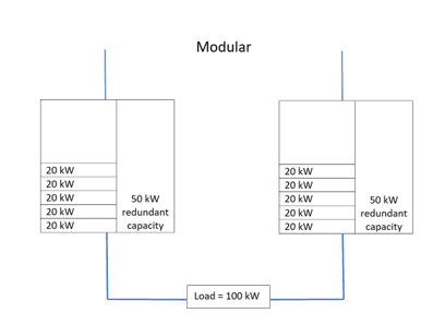
Fig.4: N+N redundant configuration for two power buses
However, the system of Fig. 4 is not ‘fully redundant’, because if one complete UPS rack fails, the other can fully support the load – but without redundancy. One solution is to choose a 2(N+1) configuration as shown in Fig.5. This provides dual bus redundancy, plus either rack will continue operating with N+1 redundancy if the other fails.
This configuration offers high availability and concurrent maintainability as well as redundancy at load and bus level. However, it does increase system complexity, as well as capital costs (and possibly operating costs if not well utilised).
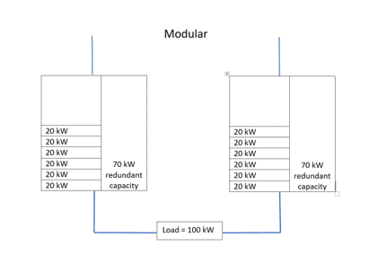
Fig. 5: 2(N+1) redundant configuration
Note that all these modular systems benefit from hot swappability. This means that a failed module can be replaced in typically half an hour or less, compared with the six hours or more usually needed to effect an in situ repair on a monolithic system. With this reduction in mean time to repair (MTTR), availability reaches ‘six nines’ or 99.9999 percent.
Total capacity of up to 400 kW can be provided by paralleling two KOHLER PW 8000DPA units. Even greater capacity can be provided by the KOHLER PW 9250DPA, which accommodates up to five 50 kW modules, or the KOHLER PW 9500DPA that accepts up to five 100 kW modules. Up to six 9250 units or six 9500 units can be paralleled, for maximum capacities of 1.5 MW (9250) or 3 MW (9500).
Above all, the modular system’s flexibility and scalability allows healthcare power system designers to meet HTM 06-01’s recommendations easily. For example, where support systems are considered high risk, the electrical supply system should be designed around a dual bus distribution architecture. Associated UPSs should therefore be arranged in an N+N or 2(N+1) configuration as appropriate. These requirements particularly apply to Group 2 Medical Locations as defined in BS 7671, where applied parts are intended to be used, and where discontinuity (failure) of the supply can cause danger to life.
In other applications, such as information technology, N+1 configurations can be used; these can be achieved with single KOHLER PW 8000DPA racks. In any case, the risk in each situation should be assessed, and an optimum solution applied accordingly.
Hot swappability also allows compliance with HTM 06-01’s requirement that, where appropriate, the UPS should have a facility to be completely withdrawn from service and replaced with no impact on normal service during the change.
KUP also supplies UPSs designed specifically to support the evacuation lifts found in hospitals. UPSs are often desirable as a secondary power source for such lifts, yet unprotected units will be damaged by regenerated currents fed back by lifts during normal operation.
KUP’s solution is its LIFT Series of UPSs; these use semiconductor IGBT controllers to electronically absorb any backfeed energy from the lift, so protecting the UPS. The controller activates immediately it detects a rise in internal DC bus voltage, and remains operational until this voltage returns to an acceptable level.
Like the UPSs and inverters that use them, batteries need care and expertise in their selection, deployment and maintenance. KUP provides VRLA lead-acid batteries as recommended by HTM 06-01, which are BS EN 60896 Pt 21 and 22 compliant, and incorporate threaded-insert connection posts and flame retardant case materials. Li-ion solutions are equally well supported if required. KUP can configure the batteries in split banks, so that UPSs can remain on line – although with reduced autonomy – with one bank, while the other is being serviced.
Suitable battery autonomies for various applications can be discussed and supplied. KUP can comply with HTM 06-01 guidelines, which state that for tertiary power supplies to clinical areas requiring a changeover period less than or equal to 0.5 s, typically in Medical Location Group 2, a battery autonomy of 3 h is required. This may be reduced to 1 h if an SPS is available within 15 s. Where the UPS battery provides tertiary power to other applications in operating theatres, the battery autonomy should provide operating theatre staff enough time to facilitate “patient closure” for all theatre cases.
Once installed, battery reliability and longevity depends heavily on good quality care. This is covered later, within the discussion about remote maintenance and monitoring.
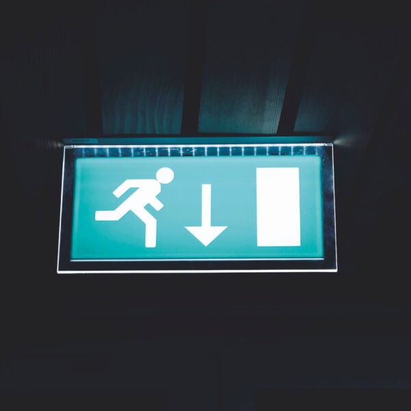
Emergency lighting
Emergency lighting should comply with BS 5266-1 and BS EN 1838. There are three areas of emergency lighting to be considered: escape, safety and standby. This has been modified by the 2016 revision of BS 5266-1, which introduced the category of ‘emergency safety lighting’. This is intended to provide additional safety for premises where occupants need not evacuate immediately in the event of a normal lighting supply failure.
Emergency escape lighting consists only of escape-route emergency lighting throughout the healthcare facility. This is the minimum requirement for all healthcare facilities. All emergency escape lighting should have a minimum duration of 3 h and should incorporate fully automatic network-testing facilities.
Emergency safety lighting should enable the occupants to remain safely on the premises during a supply loss. Emergency safety lighting power should be derived from integral battery packs (tertiary power).
For both emergency escape and safety lighting, central emergency battery units can be considered; however, additional costs for fire-rated cabling should be included in any option appraisal.
Standby lighting, as part of an emergency lighting system, enables normal activities to continue substantially unchanged for a short time until normal service is restored. It derives its power from the SPS.
Operating theatres, which are risk grade A, should have an independent tertiary power source (battery inverter unit) for the operating theatre lamp(s) and satellite lamps. The battery autonomy should be at least 3 h. Unlike other areas, the lighting level in an operating theatre cannot be allowed to reduce during a mains power outage.
Self-contained emergency escape and safety lighting products, complete with internal battery packs, are often popular with installers because they are easier to initially fit. However, accessing them in locations like high ceilings to change batteries, or individually test them to meet regulatory requirements can create challenges for facilities managers. Accordingly, the benefits to the estate management team of centrally controlled and reported power units can often outweigh their extra cost and mandatory requirement for fire-rated cabling. Additionally, centrally powered systems can much more easily be upgraded if lumen level requirements increase in the future.
KUP’s KOHLER EL static inverter series can provide complete emergency lighting protection while meeting European BS EN50171 specifications. The range includes single-phase solutions and the three-phase EL300DSP series as Fig. 6 exemplifies. All products offer 120 percent continuous overload capability, intelligent battery monitoring and a galvanic isolation transformer.
The range includes independently performance validated products that are BSI Kitemarked to BS EN 50171:2001 and BS EN-50272-2:2001. Modular units that offer the same scalability benefits as modular UPSs are also available
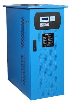
Fig. 6: KOHLER Uninterruptible Power’s KOHLER EL300DSP emergency lighting inverter
Generators
Standby generators can be connected at the intake point, or at specific LV switchboards. A generator set represents a single point of failure, and maintenance routines should be developed to reduce the risk of failure.
Best practice is that the generators should have an N+1 configuration with either two generators each capable of full load, or three generators each capable of 50% load. This not only provides opportunity for maintenance but improves overall resilience. A time delay of up to 15 s is allowed between loss of normal supply and connection of the standby generator to the supported circuits.
For onsite bulk fuel storage, the volume of diesel fuel oil stored within the day tank and arranged for gravity feed to the generator engine should not exceed the greater of 750 L or the equivalent of 10 h full load (maximum capacity) generator set runtime. Additionally, a fuel oil main reserve for 200 h full-load running for each standby generator set should be available on-site.
Environmental considerations matter as well, with noise attenuation being a key issue. The Control of Noise at Work Regulations specifies that air intake and extract noise should be attenuated so that the sound pressure noise 1 m from the enclosure/ house is less than 85 dBA. This may need to be lower in certain areas depending on the positioning and the local environmental conditions.
KUP offers ranges of single– and three-phase standby generators that provide high reliability and low costs, backed by comprehensive maintenance support. Models such as the KOHLER PW T Series – see Fig. 7 – offer acoustic noise levels compliant with the latest EC Directive 2000/14/EC. Additionally, generators can be provided in fully weatherproof, acoustic enclosures to help overcome the environmental challenges often encountered on hospital sites
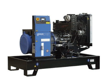
Fig.7: KOHLER Uninterruptible Power’s KOHLER PW T Series standby generator
Maintenance and support
HTM 06-01 defines five basic elements of operational management and electrical services maintenance within healthcare facilities:
- Failures response;
- Visual inspection;
- Planned preventative maintenance;
- Service/test/recorded information/ feedback;
- Condition-based maintenance.
KUP helps healthcare operators implement effective maintenance strategies based on these five elements, through their nationwide team of service engineers offering 24-7-365 support, backed by their PowerNSURE remote monitoring and management service, PowerREPORTER remote UPS monitoring, and generator remote monitoring and exercising.
PowerNSURE not only monitors battery resistance, temperature and voltage, but also runs equalisation processes to ensure correct battery charging at all times. These features maximise battery operational life, while the monitoring services also provide early warning of latent problems; allowing rectification before they can cause failures.
If a problem ever does occur, a KUP service engineer will be on site within an agreed timeframe. Additionally, visits can be regularly scheduled to perform planned inspection and maintenance.
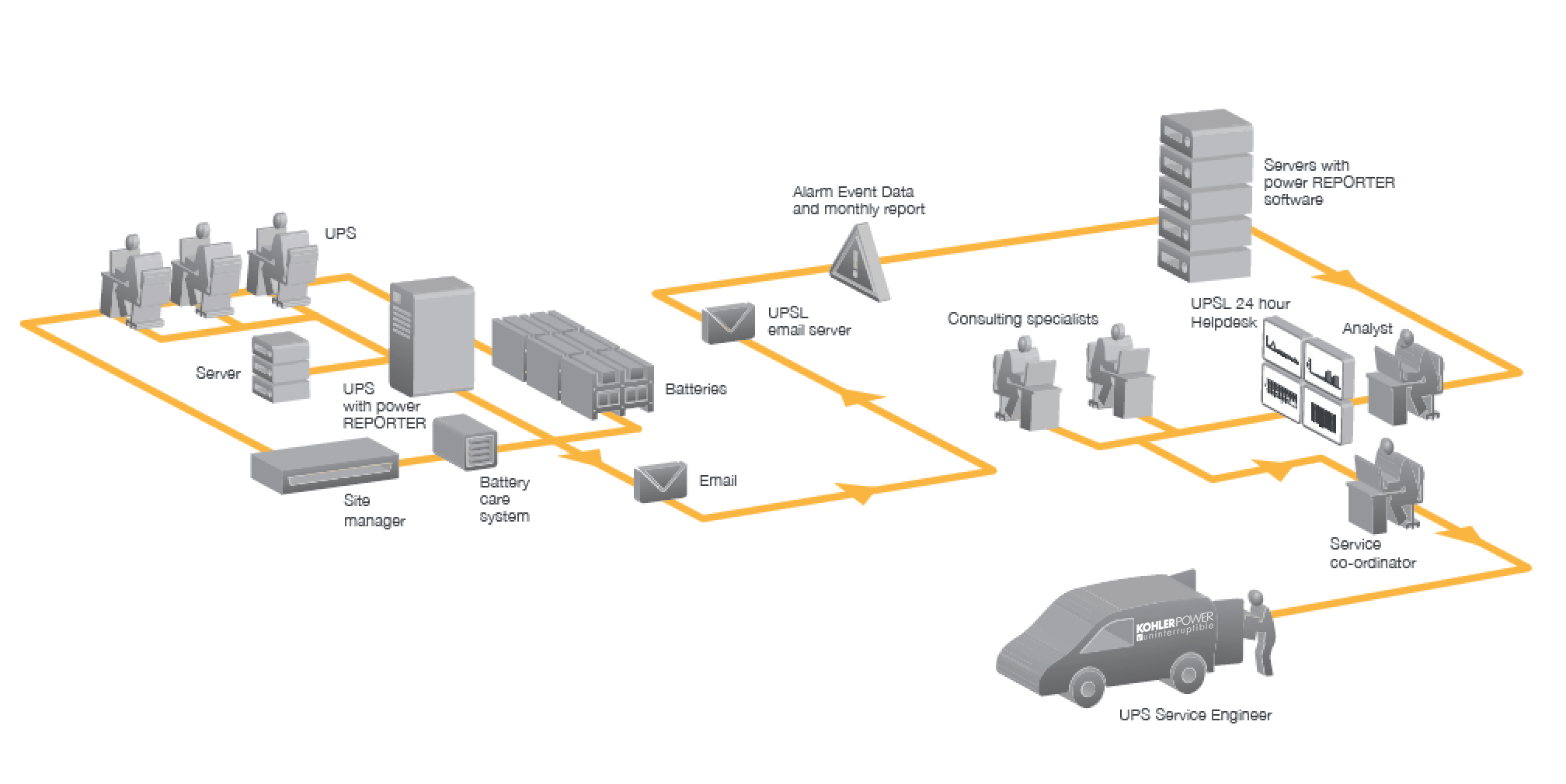
Fig.8: KOHLER Uninterruptible Power’s remote call-out facility
Conclusion
Profiling a resilient power infrastructure that cost-effectively yet adequately meets the various needs and risks of different departments across an entire healthcare estate, while complying with multiple guidelines, regulations and healthcare-specific standards can be challenging indeed.
Yet many further factors exacerbate the challenge; new systems may need integrating with legacy equipment from multiple suppliers, and finding adequate, suitable spaces for new hardware can be difficult. Maintenance must be arranged, and, with electrical demand in the healthcare sector growing between 3 percent and 6 percent year-on-year, requirements are continually changing and increasing.
While solving these issues calls for in-depth site knowledge plus expertise in numerous technical areas, many sites have been undergoing a loss of specialist experience. Accordingly, choosing a power protection equipment supplier to deliver mission-critical resilience isn’t just about the products on offer; success depends on finding a long-term, dependable partner who fully understands each site and its requirements, and can provide solutions intelligently matched to their target environments.