These notes are for information. The system should have been designed, installed and tested by competent engineers but they cover some of the points that have too often been neglected in the past.
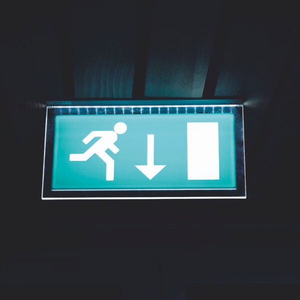
Many premises should be provided with emergency lighting systems to assist occupants to evacuate premises safely in the event of an emergency such as a fire. But emergency lighting also provides a valuable protection to guard against stumbling in the event of a sudden lack of mains illumination.
These precautions should be identified by the fire risk assessment and it is important to check if they are adequate and appropriate. In a number of cases the suitability of the system is a matter of a judgement call in which case the British standards BS 5266-1 EN 50172 and EN 1838 can provide useful guidance
Emergency lighting may be needed to enable users to locate and use escape routes and to help them to perform any necessary safety related actions such as releasing occupants of lift cars etc.
The guides to risk assessment give useful information to evaluate if reasonable precautions have been taken. These include:
Is emergency lighting needed:
3.4.4 Emergency escape lighting. People in a premise must be able to find their way to a place of total safety if there is a fire by using escape routes that have enough lighting. Where any escape routes are internal and without windows, or your premises are used during periods of darkness, including early darkness on winter days, then some form of backup to the normal escape route lighting (emergency escape lighting) is likely to be required.
(Note in the past illumination from street lights was accepted in some cases, but because local authorities now often switch street lighting off for energy saving this should be treated with caution)
Major change in BS 5266-1: 2016
Recommendations were introduced for the protection of occupants who are allowed to stay in a building during a mains supply failure referred to as Safety Lighting.
The user should consider the procedures they will be using in the event of a mains supply failure. They could decide:
- On total building evacuation, in which case no additional requirements are needed
- Or they could decide to allow some or all occupants to remain in the premises. In which case they need to decide on suitable procedures to protect them. These should be assessed by considering the risks of the premises and the type of occupants.
BS 5266-1 2016: details these procedures that could be used –
- Allowing occupants to remain in a premises for a limited time, for example cinemas and theatres
Documentation for the system should be available on site
- System plans
- Certificate of design prepared by a competent engineer
- Certificate of installation showing that the design was complied with
- Certificate of verification showing the system operated correctly (combined certificates for systems of less than 20 luminaires can be used, if the original documentation is not available a substitute report for existing buildings can be used)
- A test log book should be available showing previous test results.
The design target should have been agreed with user, the design should be performed by a competent engineer and fully documented and have system plans showing the locations of emergency lighting equipment. It should be checked that the system design meets the application requirements.
Has it been designed for the correct illumination level, does it illuminate quickly enough and provide illumination for an adequate time period for the application?
The code of practice and EN 1838 now call for:
- Escape routes 1 lux minimum on the centre line
- Open areas 0.5 lux minimum in the core area
- High risk task areas -10% of normal illumination
- Illumination should be available within 0.5 secs of supply failure in high risk task areas
- Illumination should be available in 5 secs for other risks
- Note when first introduced, light outputs of luminaires were lower and the level required for the centre line of escape routes was only 0.2 lux. This level was only adequate if the route was kept unobstructed, as if an obstruction of a similar colour had been left in an emergency condition, it was not likely to be noticed. Consequently the level for new installations was increased to 1 lux on the centre line and guidance given that existing installations should be assessed to decide if the risk of an obstruction justified increasing the illumination to the current value
- Maintained illumination should be provided in applications where the normal lighting is dimmed such as theatres, cinemas etc.
- Non maintained luminaires have to be activated by a failure of the local normal mains lighting circuit
Check the system design and installation
- Are the areas identified in the risk assessment covered by the design?
- Are the luminaires located at the specified points of emphasis?
- Is the spacing between luminaires within the design maximum values to ensure the light levels targets are met?
- Are there adequate exit signs and are they illuminated to be visible in both mains healthy and mains failed conditions (also are arrows facing the correct direction?)
- Are other fire protection systems such as call points and control panels illuminated by emergency luminaires?
- Are adequate automatic or manual testing facilities provided to enable the system to be tested safely?
Emergency lighting equipment should meet the appropriate product standards to demonstrate their fitness for purpose. Luminaires should meet BS 60598-2-22. Central battery power units should be manufactured to BS EN 50171. Ideally these components should have been tested to these standards by a trusted third party or the competent design engineer should have checked their performance and quality.
Specific elements of an emergency lighting system for consideration
Note: emergency lighting can be provided by self-contained luminaires, centrally powered battery systems or Generators. Provided the equipment meets the appropriate standards and is correctly installed and maintained will provide illumination as required.
Caution
- The appropriate plans and documentation should be provided to enable service, replacements and system extensions to be compatible with the original system design
- The completion documentation should confirm the procedures used to verify that minimum requirements of emergency illumination have been met (this is normally in the form of relevant spacing tables or computer print outs of the emergency illumination.)
- The components used should be have adequate quality and performance in accordance with their relevant product standards
Self contained luminaires can be installed in a similar procedure to normal mains luminaires but must have an unswitched mains supply to stop them discharging until the mains fails.
Caution
- Many self-contained luminaires are not third party tested the responsible engineer should be able to demonstrate –
- That the required light levels have been met. The design should identify the photometric light output in the form of a computer print out or spacing table. If these are not available on-site tests may be needed.
- The housing should be fire resistant and able to contain any battery problems.
- The system may not have appropriate testing facilities.
Existing installations may have different luminaires from the original design used as replacement units in this case the service engineer has assumed design responsibility and a check on the luminaire suitability should be made.
Central systems power a number of remote luminaires from a central unit the wiring to these luminaires
Caution
- The central power unit should be sited in a low risk location
- The wiring and connections between the power unit and luminaires should be in fire protected cables to enable the supply to be maintained during a fire condition, (The requirements are the same as for fire alarm systems.)
- Adequate and appropriate spares should be readily available to minimise down time in the event of a system fault.
Some central power units use an inverter to supply 230volts output enabling normal mains luminaires to be used.
- it is important that these systems are rated to be able to provide sufficient power to clear any distribution protective devices such as mcb’s or fuses.(this is important so that a fault in a section of the distribution network will be isolated allowing the rest of the system to continue operating)
- The inverter must be designed to match the load profile and to provide the starting surge of the luminaires this means that the design engineer must be able to match the inverter the cabling and the luminaire load.
- The inverter supply should be solely for the emergency lighting load so there are no other loads connected which could interfere with the luminaire supply-
- The product standard for central battery systems requires that the battery should have a design life of 10 years this is important as these cells are unlikely to fail suddenly but instead they gradually reduce capacity with life, the testing regime can identify this allowing for timely replacement.
- As these systems are sophisticated maintenance and service contracts should be in place with either the original equipment supplier or a specialist facilities management company.
Generators need to be specified to meet the start up time required by the application (0.5 or 5 secs.) they should also be wired in fire protected cables and engineered to give final circuit failure protection. If these conditions cannot be met alternative systems are needed to bridge the gap at a time of change over when occupants are particularly vulnerable.
Caution
- The starting time needs to be within the time limits of either 5 or 0.5 secs depending on the application.
- The regular maintenance needed includes running for one hour on 70% of load to get the engine up to full operating temperature to ensure future starts will not be prejudiced by carbon build up in the cylinders. This testing procedure can be disruptive unless carefully planned.
- The location of the generator and its fuel should be in a low risk area l
BS 5266-1 includes a check list and notes for competent engineers to use to demonstrate the suitability of the system for the application.
To simplify this process we have created an editable PDF version of this form which can be downloaded in the link below. For support in completion please contact us directly. Our emergency lighting business development manager, Ian Watts, will be happy to assist.


