Some UPSs need just simple communications capability to warn their critical load of an impending failure. Larger, more complex or widely distributed systems benefit in many ways from more sophisticated, network-based communications solutions. KOHLER Uninterruptible Power director Alan Luscombe looks at the options.
The UPS’s primary role within a data centre or ICT room is to provide instant battery backup if the mains power fails. Sometimes, this backup resource is designed to support the load for extended periods. More usually, though, its purpose is to buy time for the load to shut down gracefully, or for a generator, if available, to start up and come online.
Clearly, the UPS must communicate some type of warning signal to trigger either strategy as soon as the mains fails; otherwise, if a blackout exceeds the battery autonomy times, a system crash is merely delayed rather than prevented.
This is one fairly obvious scenario yet there are other ways in which not only the critical load but also other services such as building management systems and remote monitoring terminals can benefit from visibility of the UPS and incoming mains supply status, together with an ability to control the UPS if necessary.
However, there is no point in investing in a communications capability beyond the realistic needs of an application; accordingly, this article looks at the various options available. At the simplest level, ‘true/not true’ information can be obtained from volt-free contacts that can communication UPS status and alarms to other equipment on the same site as the UPS. Windows, Mac, Linux, Unix and other PC or network operating system variants support software that can detect these alarms and react by initiating an orderly system shutdown automatically. Figure 1 shows some typical volt-free UPS status signals.

A more sophisticated communications strategy can be implemented using the RS-232 connection available on many UPSs. This allows more detailed information to be transmitted, including data generated by UPS self-diagnostic activities. Examples of analogue values that can be measured and transmitted include:
- Inverter output voltage, frequency, current, kVA and kW
- Bypass voltage, charge/discharge current and remaining battery time
- Statistics regarding mains failures and UPS operation
The RS-232 serial connection allows the UPS to be monitored in real time as a remote computer can continuously poll it for updates. In normal practice, however, only critical alarms are continuously monitored, while operational status data is requested as needed by system administrators. The exact information profile obtained in this way from a UPS depends on the individual UPS supplier, and the software they provide to handle the serial data stream.
The RS-232 protocol is also manufacturer-dependent, as no European Standard for UPS RS-232 protocol exists.
The monitoring software is available for most operating systems, and its facilities may include:
- A graphical display of UPS status, voltage, current, load, battery voltage and frequency and more.
- Configurable responses to certain alarms, which can include broadcasts to users
- Scheduled diagnostics checks and data logging
RS-485 or full-duplex RS-422 communications can be used for longer distances, and modern UPS equipment also provides a USB port. Modbus, an application-layer serial communications protocol that operates over either RS-485 or IP links, can also be used to communicate with up to 240 devices across a common network.
Network-based solutions
Larger systems, spread over wide areas across sites that may be hundreds or even thousands of miles apart, present monitoring, management and maintenance challenges that can only be addresses with a full IP-based Wide Area Network (WAN) solution.
This is especially true if some of the sites within the network are unmanned or without a network manager. Any problems they experience could cause irreparable damage to system hardware and software without a means for rapid resolution.
The solution is to equip devices like UPSs with Simple Network Management Protocol (SNMP) capabilities, as this allows monitoring and control of every device on a WAN from a central location. SNMP is a standard protocol and part of the Transmission Control Protocol/Internet Protocol (TCP/IP) suite which allows all network devices to transmit management variables across enterprise-wide networks. SNMP is vendor- and platform- independent, and establishes guidelines for how information is collected and managed.
Network devices gather information into a management information base (MIB), from where it can be accessed by SNMP management software running within the user’s operating system.
An SNMP-enabled UPS is an intelligent device that can log events, continuously monitor power quality, report on battery status, load and temperature, and perform self-diagnostics – but this built-in intelligence creates other management opportunities as well. The UPS can handle incoming commands to control the individual devices it supplies; for example, to isolate sections of a system for security purposes, shut down some devices to save power, and manage redundancy.
Predictive maintenance also becomes possible. The UPS can log power disturbances, track battery usage, alert managers to low battery problems and track power level history. Through SNMP, this information is available across the network for immediate analysis and to detect potential problems before they cause downtime or damage.
SNMP-based networking can also be expanded to encompass multiple UPSs for optimum efficiency in load management. Information can be colelcted from, say, several dozen UPSs into a central network console to allow an integrated, large-scale control strategy. Well-managed UPS vendors typically use networking and communications to provide a remote UPS monitoring service for their customers. KUP’s PowerReporter, for example, runs on a customer’s network, continuously monitoring status and automatically detecting any error or alarm messages. If one occurs, PowerReporter emails KUP’s Service Centre with status data, any related details, and device identification. (shown in figure 2)
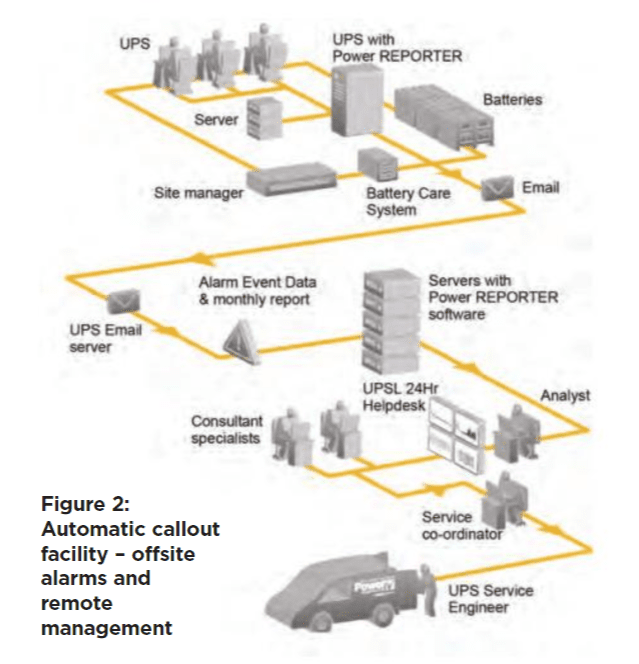
This allows the company to brief an appropriate field service technician, who can perform remote diagnostics, followed, if necessary, by a site visit to rectify the fault – all within any contractually agreed time frame.
All UPSs need some type of communications capability to warn their critical load of a power failure. For some simple systems, that’s all that’s necessary but larger, distributed and multi-site systems can benefit from more sophisticated network solutions.
As well as immediate warnings, these allow predictive maintenance, strategic analysis, early intervention from remote or third-party specialists, and advanced, centralised control strategies or large, multi-UPS systems from centralised management consoles.
Posted by: Mission Critical Power October 2017 https://missioncriticalpower.uk/