At the most general level, all modern static UPSs comprise a rectifier/charger, battery, inverter and static switch. These components allow the UPS to charge the battery when the utility supply is available, draw battery power during mains problems, and connect the raw mains directly to the load if required.
However, these components can be interconnected using either on-line or off-line topologies, allowing users to trade off power quality against cost. Below, we explain these topologies and their differences, to inform users’ UPS strategy decisions.
Note that line-interactive systems are also available; these are hybrid designs that attempt to offer a higher level of performance than conventional off-line types by adding voltage regulation to the bypass line.
Off-line UPSs
An off-line UPS configuration is shown in Fig.1. The system is shown in normal operation under mains power; note that in this mode, raw power goes directly from the utility supply, through the bypass line and static switch, to the critical load. Accordingly, off-line topology subjects the load to any incoming mains aberrations that fall within the acceptable bypass voltage limits. Usually, however, there is a degree of spike suppression and radio frequency (RF) filtering in the bypass circuit.
If the bypass voltage drops below a minimum value the inverter immediately starts if not already running, and the static switch transfers to the inverter output. These circumstances mean that a temporary break, of typically 2 – 10 ms duration, inevitably occurs during the transfer. This is less of a problem than it used to be, as most loads can comfortably ride through such a break without shutting down or suffering damage. The static switch reverts to bypass when normal power is restored.
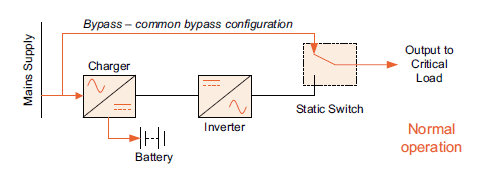
Fig.1: Off-line UPS topology
The following points summarise the key aspects of off-line topology:
- The critical load’s supply voltage is not regulated during normal operation, and it could be subjected to damaging spikes
- The power break in transferring either way between bypass and inverter may be viewed as an unacceptable risk
- Lower capital costs than an on-line system due to lower-rated components and omission of power rectifier
- Lower running costs as rectifier and inverter inefficiencies are not incurred during normal operation
On-line UPSs
Fig.2 shows typical on-line UPS topology. The obvious difference is that during normal operation, the static switch is selected to the inverter output. Accordingly, the critical load spends most of its operational life enjoying conditioned power; the ac waveform, generated by the inverter, is devoid of noise, transients, and other potentially damaging mains-born disturbances. These are filtered out in the rectifier and charger stages of the UPS as well as the inverter. The rectifier/charger generally includes an input current limit function to provide overload protection and a dc voltage shutdown mechanism to protect the battery/inverter and dc filter components.
If the mains supply does fail, the inverter can start to draw power from the battery with no interruption, as the battery is already connected to the dc bus that feeds the inverter.
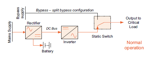
Fig.2: On-line UPS topology
The following points summarise the key aspects of off-line topology:
- Offers highest level of critical load protection – the load receives closely-regulated power at all times
- No load break when transferring between inverter and bypass in either direction
- Mains failure is transparent to the load
- More expensive capital cost than off-line
- Higher operating costs due to rectifier and inverter inefficiencies, although these have been minimised in modern transformerless systems.
Despite the extra cost, most data centres choose on-line systems, because the extra protection and continuity they provide is regarded as critical.